
How a motherboard works comes down to one role: it is the main printed circuit board that mounts every component and routes both data and electrical power between them. Copper traces etched into a multi-layer board form the buses; the CPU and the chipset decide which device talks at any moment; and the power-delivery circuit converts the supply rails into the exact voltage each part needs.
What Is a Motherboard?
A motherboard is the main printed circuit board that connects every component of a computer and routes data and power between them:
- Mounts the core parts: the CPU sits in its socket, RAM in DIMM slots, add-in cards in PCI Express slots, and drives on SATA and M.2 interfaces.
- Routes data: copper buses carry signals between the CPU, memory, expansion cards, and storage controllers.
- Distributes power: the PSU rails feed the board, which regulates and delivers the right voltage to each part.
- Fixed size: standardized form factors (ATX, Mini-ITX) set the mounting holes and slot counts.
Best for: seeing the board as the single interconnect every other component depends on, expanded in the motherboard explained guide.
What Does the Chipset (PCH) Do?
The chipset is the controller silicon that manages I/O, secondary expansion lanes, and connectivity between the CPU and the rest of the board:
- One chip now, not two: the memory controller, primary PCIe lanes, and integrated-graphics controller moved onto the CPU die back with 1st-gen Intel Core (2008), leaving a single chip.
- Intel calls it the PCH (Platform Controller Hub); AMD calls it the chipset. Both are essentially the enhanced old southbridge.
- It expands connectivity: extra USB ports, SATA ports, secondary PCIe lanes, Ethernet, and audio all hang off the chipset.
- It sets the feature ceiling: the specific chipset decides whether overclocking is unlocked and how many high-speed lanes the board exposes.
How Do Buses and Traces Carry Data?
Buses and traces are the conductive copper pathways etched into the board that carry data, addresses, and control signals between components. A trace is one thin copper line; a bus is a group of traces moving related signals together:
- The memory bus connects the CPU memory controller to the DIMM slots, moving data between the processor and system RAM at the rated DDR transfer speed.
- The PCI Express bus connects the CPU and chipset to the expansion slots and M.2 storage through serial lanes that each carry data in both directions.
- The DMI or Infinity Fabric link connects the CPU to the chipset, aggregating the traffic from chipset-attached devices into one high-speed channel.
- The SATA bus connects the chipset to mechanical and solid-state drives at up to 6 gigabits per second per port.
- The SPI bus connects the chipset to the firmware chip that stores the UEFI code the system reads at startup.
Best for: grasping why board quality matters. Trace length, spacing, and impedance are tuned during design; high-speed buses run as differential pairs (signal plus its inverse on two matched traces) to reject noise, which sets the top stable memory and PCIe speeds.
How Does the CPU Socket Connect the Processor?
The CPU socket is the mechanical connector that mounts the processor and links its contacts to the surrounding traces:
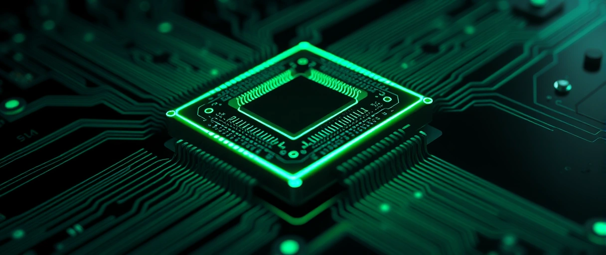
- Hundreds to thousands of contacts join the chip to the memory bus, the CPU-attached PCIe lanes, the power circuit, and the chipset link.
- Socket type fixes compatibility: Intel desktop uses LGA1700 / LGA1851 (pins on the board); AMD desktop uses AM5 (LGA) after AM4 (PGA, pins on the chip).
- A retention arm clamps the chip onto the contacts, and the integrated heat spreader passes heat up to the cooler.
Best for: the one rule that drives upgrades – a CPU only fits the socket it was designed for, so the socket (and chipset) decide which processors a board accepts.
How Do Memory Slots Work?
Memory slots are the DIMM connectors that hold the RAM modules and link them to the CPU memory controller:
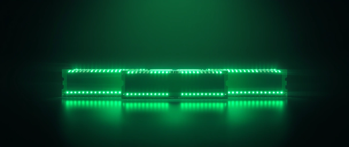
- Two or four DIMM slots on most consumer boards, arranged in two channels beside the socket.
- Dual channel: populating one slot per channel (the color-matched pair) roughly doubles memory bandwidth over a single stick.
- One generation only: a board is DDR4 or DDR5, never both – the notch and electrical design differ (see DDR4 vs DDR5). DDR5 splits its channel into two 32-bit sub-channels.
Best for: knowing why the manual’s slot-population order matters – it sets the capacity and bandwidth the board can actually reach.
How Do PCIe Slots Handle Expansion?
PCI Express slots are the expansion connectors that link graphics cards, storage, and add-in cards to the CPU and chipset over serial lanes:
- Lane counts (x1, x4, x8, x16) set the bandwidth; the long x16 slot wires straight to the CPU for the graphics card, while shorter slots run off the chipset.
- Per-lane speed by generation: PCIe 4.0 is about 2 GB/s per lane, PCIe 5.0 about 4 GB/s per lane (a full x16 5.0 link is roughly 128 GB/s).
- M.2 shares the bus: M.2 NVMe slots also draw PCIe lanes, and on some boards an M.2 slot shares bandwidth with a SATA port, so filling it can disable that port.
Best for: planning a build – the slot and lane layout decides how many high-bandwidth devices run at full speed at once.
How Does the Board Deliver Power (VRM, 24-Pin, 8-Pin EPS)?
The board delivers power through a voltage regulator module (VRM) that converts the supply voltage into the precise level each component needs:
- 24-pin main connector: feeds the board and its slots with the 3.3 V, 5 V, and 12 V rails.
- 8-pin EPS connector(s): deliver dedicated 12 V power to the processor.
- The VRM steps 12 V down to ~1 V for the CPU cores, switching millions of times a second through power stages, inductors, and capacitors arranged in phases.
Best for: high-core-count CPUs and overclocking – more and higher-rated phases give cleaner, steadier current under heavy load.
What Are the I/O Ports and Onboard Headers?
I/O ports and onboard headers are the connectors that link the board to external peripherals and to internal case components. The rear panel faces outside the case; headers are pin clusters for cables routed inside:
- USB ports and headers connect keyboards, storage, and front-panel USB, ranging from USB 2.0 to USB 3.2 and USB-C at up to 20 gigabits per second.
- Display outputs such as HDMI and DisplayPort carry video from the processor’s integrated graphics when no discrete card is installed.
- Audio jacks and the front-panel audio header connect speakers, microphones, and case headphone ports to the onboard audio codec.
- Fan and pump headers supply power and speed control to case fans, the CPU cooler, and liquid-cooling pumps.
- The front-panel header connects the case power button, reset button, and status LEDs to the board.
Best for: matching a board to a case. Extra headers carry RGB, more SATA, and TPM; larger boards simply offer more rear ports and headers than compact ones.
What Do the BIOS/UEFI Chip and CMOS Battery Do?
The firmware chip and the CMOS battery are the components that store the startup code and retain the board’s configuration:
UEFI firmware chip
CMOS battery (CR2032)
Why UEFI, not BIOS
Best for: understanding why a board remembers your settings and clock across power cycles, and how to recover from a bad setting by clearing CMOS.
How Many Layers Does the PCB Have?
The motherboard PCB is a multi-layer board that stacks several copper layers separated by insulating fiberglass:
- 4 to 8 layers on a typical consumer board; high-end boards reach ten or more.
- Signal vs plane layers: signal layers carry data and address traces, while inner power and ground planes distribute voltage and shield the PCIe and memory buses from noise.
- FR-4 substrate: the base is FR-4 fiberglass laminate (woven glass plus epoxy), chosen for insulation and mechanical strength.
Best for: seeing why premium boards add layers – faster signals and denser routing need more ground planes to stay stable.
What Are the Major Motherboard Components and Functions?
The table below lists the primary motherboard components and the defined role each plays in connecting and powering the system:
| Component | Function |
|---|---|
| CPU socket | Mounts the processor and links its contacts to the memory bus, PCI Express lanes, and power circuit |
| Chipset (PCH) | Manages input-output, secondary PCI Express lanes, USB, SATA, and connectivity beyond the CPU |
| DIMM memory slots | Hold the DDR memory modules and connect them to the CPU memory controller |
| PCI Express slots | Accept graphics cards and add-in cards over serial expansion lanes |
| VRM and power connectors | Convert and distribute regulated voltage to the processor, memory, and slots |
| UEFI firmware chip | Stores the startup code that initializes hardware before the operating system loads |
| CMOS battery | Retains the real-time clock and firmware settings when the system is unplugged |
| I/O ports and headers | Connect external peripherals and internal case components to the board |
Last Thoughts on How Motherboards Work
How a motherboard works comes down to one role: it is the central interconnect that joins the processor, memory, expansion cards, and storage through buses of copper traces while distributing regulated power to each. The chipset extends connectivity over the DMI link, the VRM converts voltage, the UEFI chip and CMOS battery handle startup and settings, and the multi-layer FR-4 PCB keeps every high-speed signal stable.
Readers can continue with the guide to motherboard form factors, the explanation of motherboard chipsets, or the process for choosing a motherboard. The broader computer hardware guide places the board within the full component picture.
Key Takeaways:
- The motherboard is the central interconnect, the main printed circuit board that links every component and routes data and power.
- The chipset manages connectivity, expanding USB, SATA, and secondary PCI Express lanes beyond what the CPU provides directly.
- Buses made of copper traces carry the memory, PCI Express, SATA, and chipset signals between components across the board.
- The power-delivery system converts voltage through the VRM, fed by the 24-pin main and 8-pin EPS connectors from the supply.
- The UEFI chip and CMOS battery store the startup code and retain the configuration the board reads each time it powers on.
- The multi-layer PCB stacks copper planes, routing thousands of connections while keeping high-speed signals electrically stable.
Frequently Asked Questions (FAQs)
What is the main job of a motherboard?
A motherboard connects every computer component and routes data and electrical power between them. It mounts the CPU, memory, and expansion cards on one printed circuit board so the system operates.
What does the chipset do on a motherboard?
The chipset manages input-output and connectivity, expanding the USB ports, SATA ports, and secondary PCI Express lanes available beyond those the CPU provides directly.
What is the difference between the 24-pin and 8-pin connectors?
The 24-pin connector supplies main power to the board and its slots, while the 8-pin EPS connector supplies dedicated 12-volt power to the processor through the VRM.
Why does a motherboard need a CMOS battery?
The CMOS battery supplies current that preserves the real-time clock and UEFI firmware settings when the computer is unplugged, so the board retains its configuration.
How many layers does a motherboard have?
Consumer motherboards use four to eight copper layers, and high-end boards use ten or more, stacking signal, power, and ground planes separated by fiberglass insulation.
What carries data across a motherboard?
Copper traces grouped into buses carry data across a motherboard. The memory bus, PCI Express bus, SATA bus, and chipset link move signals between components.
About the author

Nizam Ud DeenFounder and Tech Blogger
Muhammad Nizam Ud Deen Usman is the founder of theCoreiTech and the author of The Local SEO Cosmos. He has worked in search since 2014 as an SEO consultant for eCommerce stores and local businesses, specialising in eCommerce SEO, local SEO and technical SEO, and runs SEO Academy and the SEO Community from Multan, Pakistan. He also founded ORM Digital Solutions, a digital agency serving medium and large businesses, and holds a degree from the University of Education, Lahore (Multan Campus). Plerdy lists him among its Best 20+ SEO Experts in Pakistan. Nizam started theCoreiTech in 2012 to make computers easier to understand and use for everyone. More of his work is at nizamuddeen.com.
